INSULATION MONITORING SYSTEM
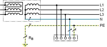

Design of IT System
The IT system is supplied by an independent supply source like
- Distribution transformer for industrial purposes
- Control transformer
- Generator, power set
- Battery
- UPS converter
- Solar panel
Advantages of an IT System
- Increased Economic Efficiency
- Increased Operational Efficiency
- Optimized maintenance
- Extensive Protection against Fire
- Enhancement of Accident
- Higher Permissible Earthing Resistance
Insulation Fault in an IT system
- In IT systems (standard-compliant term for unearthed systems) the first fault does not have any negative influence.
- The first fault does not cause unwanted system shutdowns.
- A double insulation fault at different conductors is the same as a short-circuit.
In this case, fuses are protective devices

INSULATION MONITORING DEVICE
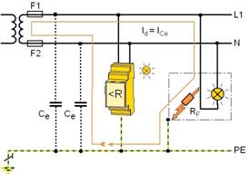
An insulation monitoring device monitors the ungrounded system between an active phase conductor and earth. It is intended to give an alert(light and sound) or disconect the power supply when the impedance between the two conductors drops below a set value, usually 50 kΩ.
Working Principle
Insulation Monitors superimpose a measuring signal, generated by signal generator G. On the occurrence of an incipient insulation fault, the measuring circuit between system and earth closed via the fault RF causing a voltage drop across the measuring resistance Rm, which is processed and evaluated by electronic circuitry. If the voltage drop exceeds the set value proportional to insulation resistance, an alarm is given. The signal has a DC component which is used to charge the system capacitances, thereby ensuring that the signal goes through the incipient fault. The nature of the measuring signal is very important as it should not affect operation of devices such as switched mode power supplies, computers, variable frequency drives etc. Further, the harmonics and other disturbances created by these devices, presence of filters connected to the system should not affect the measurement of the insulation fault. The insulation monitor provides in advance, information for effective preventive maintenance thereby ensuring the availability of power supplies. It also prevents shock hazards in small and medium size low voltage power supply and distribution system. |
 |
Factors inflencing Measuring Technique
- DC voltages in the system
- High system leakage capacitances
- Variable, low frequencies
Active Measuring Principle
|
DC measuring voltage (with inverter stage) |
AMP measuring principle (BENDER Patent) |
Principle |
Superimposition of DC voltage |
Superimposition of an Adaptive Measuring Pulse |
Application |
Pure AC systems |
Universal for all IT systems (AC, AC/DC, DC) in particular for systems containing converter drives |
Features |
For small leakage capacitances |
For systems with high system leakage capacitances |
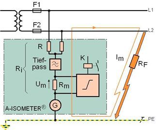
Construction
Operation
- The insulation monitoring device is connected between the phase conductors and earth.
- Continuously monitors the insulation resistance between the IT system and earth (PE)
- The measuring voltage UG generated by G is superimposed onto the system via the coupling R,a low pass and the measuring resistance Rm.
- An insulation fault RF closes the measuring circuit.The measuring current Im is flowing.
- Im causes a voltage drop Um proportional to the insulation fault RF at the measuring resistance Rm.
- Optically signals a drop in insulation resistance below a minimum value
- Must comply with the requirements of the product standard for insulation monitoring devices IEC 61557-8.
Product Overiew
 |
Device Selection Check List
- Nominal voltage?
- AC, DC or AC/DC nominal voltage?
- Main circuit, control circuit or special application?
- System leakage capacitance?
- Response values?
- Expansion to an insulation fault location system?
- Special ambient conditions?
Applications
Scope of appl. |
Application field |
Typical device |
Standards and regulations |
Typical |
control circuits |
IR125, IR420,IR425 |
DIN EN 60204-1 (VDE 0113-1) :1998-11, |
Railway |
Signal towers, |
IRDH265, IR125, |
DIN EN 50122-1 (VDE 0115-3):1997-12, |
Construction |
Mobile generators |
IR423 |
DIN VDE 0100-704 (VDE 0100-704): 2001-05, DIN VDE 0100-551 |
Mines |
All systems > |
on request |
DIN VDE 0118-1 (VDE 0118-1): 2001-11, |
Chemical |
500 V IT systems |
IRDH275 / |
Namur |
Electric |
Charging Systems |
on request |
DIN EN 61851-1 (VDE 0122-1): 2001-11 |
Potentially |
Industrial trucks, |
IR425 |
DIN EN 60079-14 (VDE 0165-1): 2004-07, |
Furnaces |
|
on request |
DIN EN 50156-1 (VDE 0116-1): 2005-03 |
Fire brigade |
Fire-fighting |
IR470LY2-4061 |
DIN 14867:2005-09 |
Airports |
Aviation ground |
IRDH1065, |
DIN V ENV 50231 (VDE V 0161-231): |
Variable Speed |
Main circuits |
IRDH275, |
DIN EN 50178 (VDE 0160):1998-04 |
Lifting + hoisting |
Control circuits |
IR125, IR420, |
DIN EN 60204-32 (VDE 0113-32):1999-06, IEC |
Industrial robots |
Control circuits |
IR425 |
DIN EN 60204-1 (VDE 0113-1):1998-11, |
Scope of appl. |
Application field |
Typical device |
Standards and regulations |
Pwer plants/ |
Battery systems |
IRDH275, IRDH375 |
DIN EN 50272-2 (VDE 0510-2): |
Medical |
Rooms of Group 2 |
107TD47 |
DIN VDE 0100-710 (VDE 0100-710): |
Military |
Mobile generators |
IR140RS |
DIN VDE 0100-551 (VDE 0100-551): |
Construction |
Mobile generators |
IR423, |
BGI 867, DIN VDE 0100-551 |
Pipeline |
Mobile generators |
IR423, |
GW 308, 8.00 - Annex 2 |
Ships |
Control systems |
IRDH275, |
DIN EN 60204-1 (VDE 0113-1):1998-11, |
Ships (Navy) |
Submarines, |
IRDH275, |
ASTMF 1134-94 (Reapproved 2002),ASTMF |
Safety |
Communal |
on request |
DIN EN 50172 (VDE 0108-100): 2005-10 |
Solar systems |
Solar power plants |
IRDH275,IRDH375 |
DIN IEC 64/1123/CD (EVDE 0100-712): |
Open cast mining, |
Conveyor systems |
on request |
DIN VDE 0168 (VDE 0168): 1992-01 |
Traffic engineering |
carriage, |
IR5002, |
DIN VDE 0115-1 (VDE 0115-1):2002-06 |
Benefits
Extended maintenance-free periods |
 |
![]()
![]()
![]()