
HOSPITAL SAFETY SYSTEMS
| Need for Electrical Safety in Hospital » The patient`s natural reactions to hazards are reduced or switched-off » The heart muscle is highly sensitive to electric currents (currents > 10 µA) » The insertion of catheters and the like into the body may reduce the electrical resistance of the skin » Body functions are temporarily or continuously supported or substituted by medical electrical devices » Fire and explosion risks through the use of anaesthetics, disinfectants or cleaning. » Even small currents flowing through the human body put the patients life and health at risk. » The availability of the power supply must be guaranteed, even under fault conditions. |
 |
Power Supply Group definitions in medically used Rooms according IEC 60364-7-710
| 710.3.5 Group 0 | 710.3.6 Group 1 | 710.3.7 Group 2 |
|---|---|---|
| Medical location where no applied parts are intended to be used | Medical location where applied parts are intended to be used as follows: • Externally • Invasively to any part of the body, except where 710.3.7 applies |
Medical location where applied parts are intended to be used in applications such as intra-cardiac procedures, operating theatres and vital treatment where discontinuity (failure) of the supply can cause danger of life |
| Massage room | • BedroomHaemodialysis room • Physiotherapy room |
• Operating theatre • Heart catheterization room • Intensive care room • Premature baby room |
 |
 |
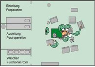 |
Medical IT System in Group 2 Locations
In group 2 medical locations, the medical IT system shall be used for circuits supplying
» Medical electrical equipment
» Systems intended for life support
» Surgical applications
» Other electrical equipment located in the "Patient Environment"
The IT system is supplied by an independent power source, e.g.
» Distribution / isolation transformer
» Control-power transformer
» Generating set
» Battery
» Inverter of an UPS
The IT system has no direct connection between live conductors and earth
» All exposed conductive parts of the electrical installation are earthed
» IEC 60364-7-71:A permanent insulation monitoring device must be designed to indicate the first occurrence of a live mass or earth fault; it must trigger an audible or visual signal.
Need for Medical IT System
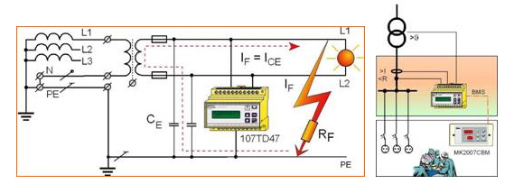
Insulation Fault
» In the event of an insulation fault RF only a very low current ICe flows
» Fuse does not trip
» In the event of a single-pole earth fault, the power supply is guaranteed
» No interruption of operation
» An Alarm is indicated if an A-ISOMETER is installed
Leakage Current
» The IT system is a small local network with low leakage capacitances.
» The fault current is limited by the body impedance, the earthing resistance and the high impedance of the fault loop.
» Hazards to persons and equipment arising from high fault currents are reduced.
Fire Risk
» A small current flows limited by the high impedance of the fault loop.
» Considerable less fire risk
» Increased protection for persons and equipment
REQUIREMENTS OF MEDICAL IT SYSTEM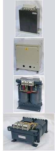
Protection against Dangerous Overloads and Insulation Failure
Requirements for Power Supply Transformer
» Transformers shall be
» installed in close proximity to, inside or outside, the medical location
» placed in cabinets or enclosures to prevent unintentional contact with live parts.
» Rated voltage Un on the secondary side of transformers ≤ 250 VAC
» Transformers according IEC 61558-2-15, with additional requirements:
» The leakage current of the output winding to earth and the leakage current of the enclosure, when measured in no-load condition and the transformer supplied at rated voltage and rated frequency, ≤ 0.5 mA.
» Rated output of the transformers 0.5 kVA … 10 kVA.
» For three-phase loads with an IT system a separate three-phase transformer shall be provided for this purpose with output line-to-line voltage not exceeding 250 V.
» IEC 61558-2-15 Safety of power transformers, power supply units and similar
» Part 2-15: Particular requirements for isolating transformers for the supply of medical locations:
» short circuit voltage ≤ 3%
» no-load input current ≤ 3%
» inrush current ≤ 12 x rated input current
» Single phase transformers
» ES0710 series
» acc. to IEC 61558-2-15
» 1…10 kVA
» Vertical or horizontal version, or installed in an enclosure
Monitoring of Transformer
» Monitoring of overload and high temperature for the medical IT transformer is required
» But no circuit breaker for protection against overload and overcurrent should be used (risk: unexpected tripping of the fuse)
» Overcurrent protective devices (MCB) should only be used for short-circuit protection.
» If too many medical electrical devices are in use in an operating room, the information will be displayed on a remote indicator if provided.
Requirements for Insulation Monitoring Device
» For each group of rooms serving the same function, at least one separate medical IT system is necessary.
» The medical IT system shall be equipped with an insulation monitoring device in accordance with IEC 61557-8 with the following specific requirements:
» a.c. internal impedance > 100 kOhm
» the test voltage ≤ 25 V d.c.
» injected current ≤ 1 mA peak, even under fault conditions
» indication when insulation resistance ≤ 50kOhm
» a test device shall be provided
» The insulation monitoring device (IMD)
» signals the first fault (RF < 50 kOhm)
» provides advance information for the medical and technical staff
Hence the essential requirements for Medical IT System are Monitoring of Load, Temperature and Insulation
 |
|---|
Requirements for Remote Alarm Indications » For each medical IT system, an acoustic and visual alarm system shall be arranged at a suitable place so that it can be permanently monitored by the medical staff: |
|
 |
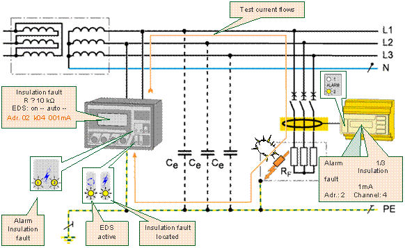
Insulation Fault Location
» The problem
» In intensive care locations several socket-outlets are arranged at every patient place, sometimes up to 24 socket outlets and more
» In an intensive care unit with 4 beds, for example, these are more than 90 socket outlets
» In intensive care units usually no technical experts are present, but medical personnel
» If a defective device causes an insulation fault, it will be very difficult to locate the associated socket outlet
» In order to guarantee the patient's safety, the insulation fault must be found as quick as possible.
» The solution
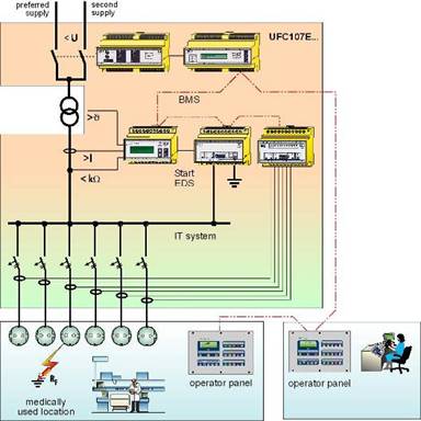
» Insulation fault location system EDS474
 |
|---|
Functional Diagram of EDS System
 |
|---|
Benefits
» Ungrounded Power Systems according to IEC364-7-710
» Fault location systems offer precise and fast localisation of defective electrical equipment offer and guarantee a higher protection for patients and staff
» Modern and sophisticated indication panels and visualization possibilities offer precise and fast information to medical and technical staff
» Testing the electrical safety of medical electrical equipment acc. to IEC 62353 / 60601-1


